Linear Motors
An Innovative tubular three-phase low voltage (24/48 V) iron core technology to provide highest dynamic performance in the smallest product footprint
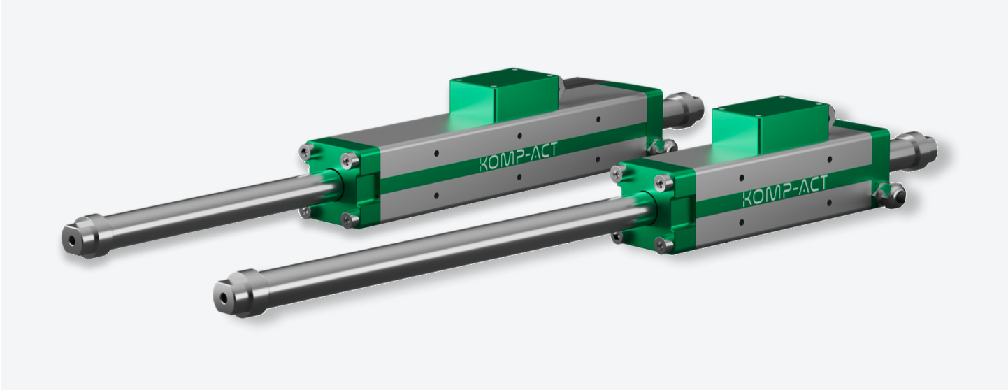
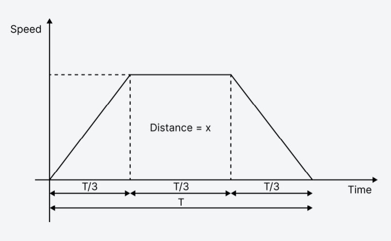
The electronic controller used in conjunction with KOMP-ACT linear motors automatically calculates the target speed and position profile in function of the desired motion parameters (mass, extension and retraction speed, cycle rate, etc.).
The speed profile is trapezoidal and computed in order to ensure maximum efficiency in terms of heat generated. This entails a specific timing for acceleration and deceleration of the device, taking into account all factors linked to the application. Thus obtaining the maximum cycle rate for a given applied mass and desired speed.
Technology
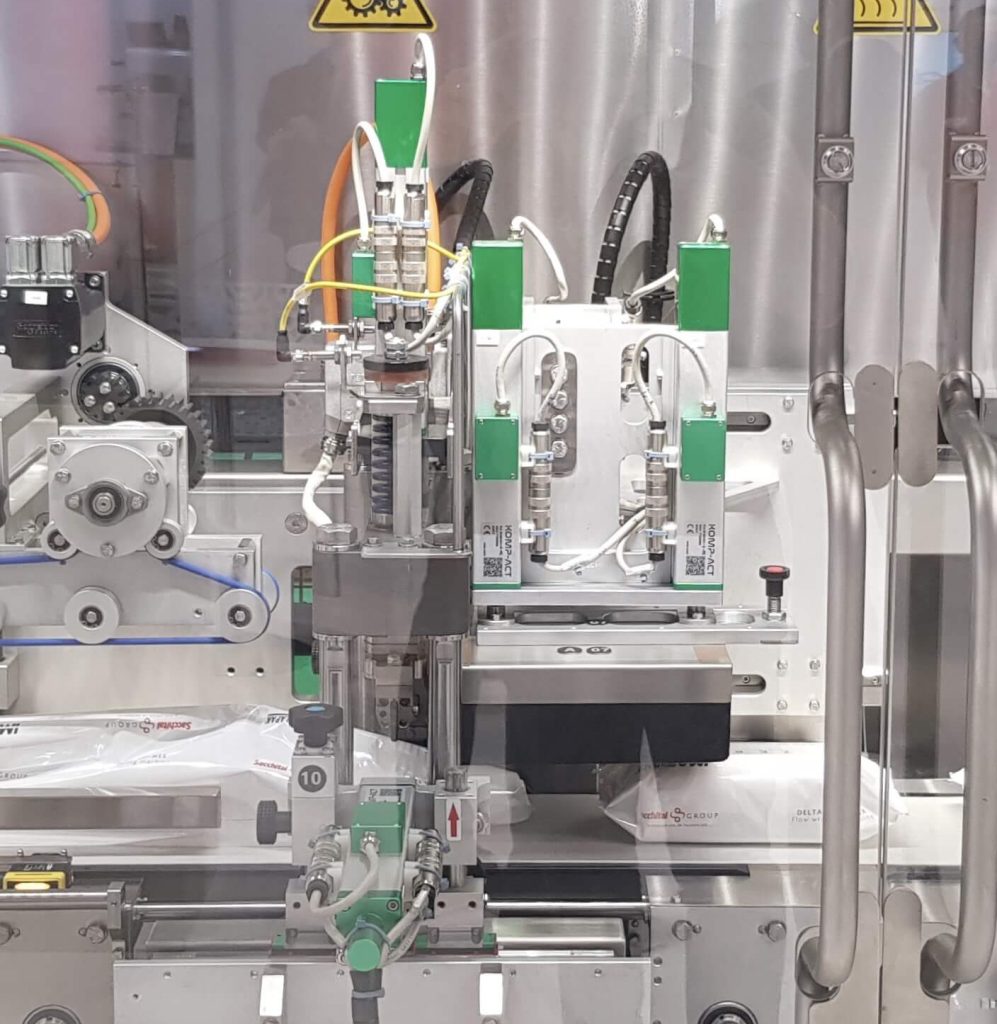
The Age Of Electric Machines Has Arrived
Traditional electromechanical actuators have permeated factories during the industrial revolution, as a core component essential to automated operations. However, these devices require mechanical transmission elements like ball screws, toothed belts, or gearboxes to move the shaft, wasting energy and increasing the cost of operation.
After years of research, we have finally been able to use electromagnetic technology into our state-of-the-art electric machines. The age of electric machines is here, ready to replace your old factory technology.
Our Edge: An Iron Core
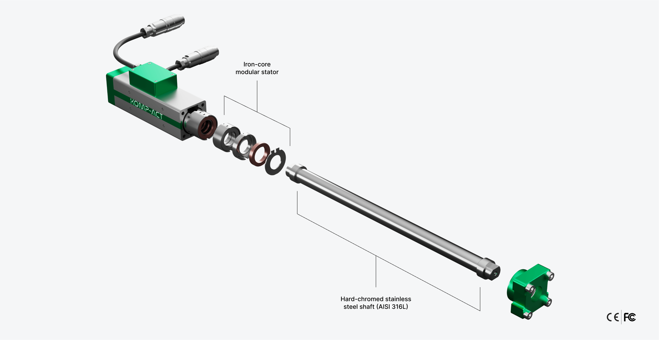
Our main innovation consists in the use of modular tubular linear motion technology with an iron core 3-phase stator which provides higher continuous force density and better heat dissipation with respect to ironless technology, thus enabling higher dynamic performance.
In addition, it reduces the amount of copper needed to produce force, resulting in lower ohmic resistance and high energy efficiency du to low power losses (copper losses).
Plug & Play
Never Been So Simple To Use
Thanks to their complete built-in design, our actuators do not require any additional accessories unlike other similar solutions, enabling customers to achieve significant space and assembly time savings.
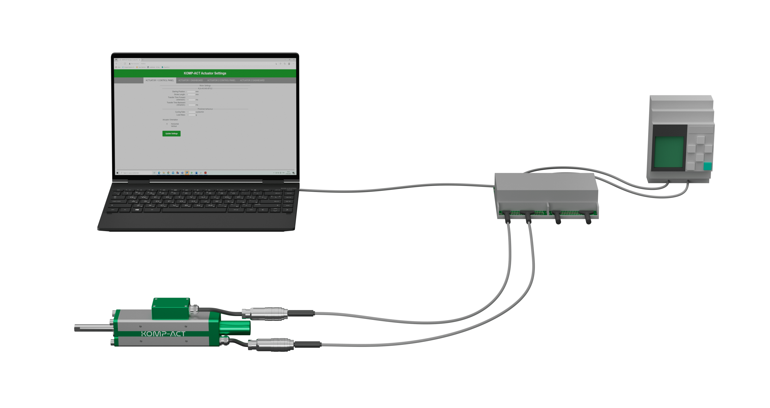
KOMP-ACT electric actuators have two cables: power and command which are connected to the electronic controllers.
Two electric actuators can be connected and managed by one single controller. The actuators settings can be changed directly with the field bus or through the web server interface, accessible by connecting a Windows laptop to the controller with a USB cable.
FAQs
Most frequent questions and answers
Pneumatic and KOMP-ACT electric actuators are not equivalent technologies. We have replaced 25 mm pneumatic actuators with a 70 N electric actuator. This is because our actuator does not have any internal friction or dynamic effect that depends on the speed of the pressure built up in the pneumatic chamber. Please contact us at sales@komp-act.com and ask for the application questionnaire.
We do usually require the application to be described in detail such as the mass of the object to be moved, the speed or the desired transfer time, the cycle rate, etc… Then we are able to provide the best solution.
For normal application and with a supply voltage of 48V, an actuator will require a DC current of around 3A from the power supply. Depending upon the application one KOMP-ACT electric actuator has an electricity cost ranging from 10 to 43 Euro per year.
All our products are CE marked.
Once the power is turned off, if in horizontal position, the actuator is moved to the base position (shaft retracted) and all movements are stopped. If in vertical position, the behaviour of the actuator would depend on the weight of the attached object. When the system is off, the settings of the application are kept saved on the memory of the actuator and are loaded on the next power on.
If the actuator has to stay in a definite position when the current is turned off we can also add a magnetic lock.
One way to command the actuator is via a digital I/O signal (12-24V). A high state (12-24V) drives the actuator forward (extension movement) and it stays in this position. When the input signal goes back to 0 V (low state), the actuator moves backward (retraction position) and stays in that position until the high state signal is given again.
A second approach is using a fieldbus communication protocol. By sending a value to the correct register, you can simulate the same behaviour as with the digital pin.
The parameters of the movements can be set through a web server interface or directly by using the fieldbus. Fieldbus allows an “on the fly” approach to configuring parameters instead of having to use the websever.
An initial calibration is done automatically through the first drive instruction sent by the PLC. Nothing is needed to be done by the user.
These parameters are linked to the control system of the actuator. The parameters that are set by default already cover most applications. Nevertheless, for more specific needs or precise movements, there is the possibility to tune these parameters. For more information consult the user manual or ask the support via sales@komp-act.com.
There are two different types of output to be expected from the actuator, one is in the form of digital signals that allows you to verify whether the stroke was done correctly as well as for the calibration check. A second type of output can be retrieved using the fieldbus, and it gives the possibility to extract multiple data from the actuators, from position to current as well as information regarding the status of the movement.
The actuator has a relative encoder. An automatic calibration is done at each power up to ensure an overall absolute physical positioning. At the power up the actuator retracts until i reaches the mechanical index and then advances to the desired starting position.
The actuator has an accuracy of +/- 0.5mm (accuracy in our case is referenced to the target stroke sent by the PLC).
It means that if, for instance, the PLC sets a stroke of 80 mm, we can guarantee that the shaft position will be between 79.5 and 80.5 mm.
Copyright © KOMP-ACT SA | 2022
